© 2008-2009, Synthetic Neurobiology Group, MIT
Media Lab/BCS/BE, MIT.
Contact
info: Ed Boyden, esb@media.mit.edu
IMPORTANT: in recent years optogenetics hardware has exploded commercially, and a wide variety of lasers and LEDs are available from a wide variety of manufacturers, with attachments optimized for different in vitro and in vivo neuroscientific purposes. For current part numbers, we suggest looking at recent papers, either using your species of interest or in a similar species, as the fastest way to find parts of interest. We leave this document up because the principles described are still of general interest.
0.
Introduction
This
document describes systems for in vivo light delivery that are inexpensive and
relatively easy to use. The goal is to provide the least expensive, most
current, helpful information about systems you can use for in vivo optical neuromodulation. We
will try to update this document every now and then, so that what you see below
represents the best practices of the field. Please note, part numbers for
products are liable to change at any time; contact the manufacturer for
updates, and please notify the authors of this white paper as well. Feedback always welcome!
1.
Fiber-coupled lasers
1.a. Laser vendors
You
can order pre-fiber coupled lasers from Shanghai Laser (http://www.lasercentury.com/; click on
“Fiber Coupled Laser” under “Products”), OptoEngine
(http://optoengine.com/default.aspx),
or other inexpensive laser companies. 473 nm can hit ChR2 or Mac, 532 nm
can hit Arch or Halo (green lasers are the cheapest), and 593 nm can hit Arch
or Halo (but these molecules can also be green light driven, and green lasers
are many times cheaper than yellow ones). 632, 640, and 655 nm red diode
lasers are also available, for red-light driving. You can specify the
fiber diameter (e.g., 100 or 200 microns wide, multimode fiber, might be
typical, although you may want to go to 50 microns or 400 microns, or even to
other values, for specialized experiments).
These lasers tend to run around $500-$1500 (a bit more for
higher powers or odd colors) at the low end, and $1500-$3000 at the high
end. These are the lasers that we’ve used in most of our research.
Very important: quality can vary from laser to laser
for such inexpensive vendors. Before buying any lasers, ask to see
oscilloscope traces of the pulse shapes that are exhibited in both short (e.g.,
1 ms, in 10 Hz trains) and
long (e.g., 10 seconds, 1 minute, 1 hour) laser pulses. Although part
numbers are always evolving, the following tips may help: The lasers are
often available with “low noise” and “temperature stabilization” options (e.g.,
for Shanghai Laser, try requesting the TB temperature compensation option; for OptoEngine, try the “<1%”
variability lasers, which at the time of this web page writing are coded
“FN”). It is a good idea to find out the return policy, and to test the
lasers (with a photodiode or power meter connected to an oscilloscope) during
the return period, to make sure its pulse shapes, and stability over
experiment-timescale durations, are appropriate for your work. It’s
really important to have at least one high quality power meter in your lab; for
example, we have some Thorlabs
PM100D power meters with S140C integrating sphere detectors; we also have some
Newport power meters in the 1918-C line with 818-SL detector and an OD3
attenuator option. Validate the laser under when pulsed at different
frequencies and also when it’s left on for many minutes or even hours at a time,
reading out the pulse amplitude and timecourse
on an oscilloscope.
Other companies in the space are (we ourselves have not tried
all of these) are Crystalaser,
Laserglow, RGBLase (http://www.rgblase.com/), http://www.thinklasers.com/fiber-coupled-lasers.html,
Shanghai Dream Laser (not the same as Shanghai Laser!), and OEM Laser
Systems. It’s worth comparison shopping.
1.b. Laser considerations
For
ease of use, you will likely want to drive the laser with a digital computer
pulse, e.g. a TTL pulse. It’s sometimes good to get a TTL-triggerable laser that is more
powerful than what you think you need, but purchase with an analog power knob
so you can precisely dial down the amplitude to the level you want. That
is because coupling of lasers to downstream fibers and devices results in light
loss.
How
do you calculate the power you need? Assume you want the radiant flux out
the tip to be 200 mW/mm2.
For a 100 micron diameter fiber attached to a 532 nm laser, and a desired
irradiance at the tip of 200 mW/mm2,
the power needed at the tip would be pi * (0.05 mm)2 * 200 mW/mm2 = 1.5 mW. So with a laser-fiber
coupling efficiency of 50%, you’d need 3 mW…
but in practice, the losses are always greater, especially if you have
splitters, connectors, etc. downstream. So get something more powerful to
be safe. We often get lasers that are 50, 100, or even more in power, and
then dial them down to a small fraction of the maximum amplitude, using the
analog power knob. (You can also split the power from one laser into
multiple fibers, but that’s another story…)
NOTE:
Getting a laser that is much much
higher power than what you need, however, may be maladaptive, since the
resonant crystal in the laser may be tuned for the heating that would result
from the higher power levels that the laser was made for. Then, pulsing
the laser at a low frequency could result in poor turn-on times, as the laser
will not heat adequately. There is a
tradeoff here. Diode-pumped solid state
lasers (DPSSLs) are designed so that the crystal heats up, expands, and then
reaches the proper length for lasing at the optimal wavelength. More expensive lasers will have active
thermal stabilization to compensate for such variability.
You
can also leave your laser on, and use a fast shutter to open and close a gate
in front of the laser. This may be
preferable for some applications where power stability is very important.
In
addition to TTL pulse control, you can also try analog control (e.g., at 10
kHz/30 kHZ frequencies) –
which will let you modulate the light power by an analog light source, e.g. one
that is continuously varying. Note that analog controlled lasers should
be calibrated so you know what the output power is, as a function of the analog
input. Analog controlled lasers do require more complex electronics to
activate them, e.g. a NiDaQ
or Digidata analog out
port. The advantage is you can dial in very complex waveforms, e.g.
sinusoids. If you desire such a protocol, get a high quality laser (e.g.,
with temperature stabilization, etc.).
1.c. Laser connecting
Your
fiber will likely eventually break, in which case you will need to attach a new
fiber to the laser. Be sure that you know what connector type (FC or SMA)
you ordered when you bought the laser; you should order a connector kit (e.g.,
from Ocean Optics or Thorlabs
or other sources) so that you’re ready to repair the fiber or add a new
connector if the fiber breaks. Attaching a new connector is very simple
— you can download the Thorlabs
“Polishing and Connectorization
Guide” – just Google those terms and you’ll find the PDF, or you could try
this link here: http://www.thorlabs.com/Thorcat/1100/1166-D02.pdf.
The SMA connector is common, but if you’re
using a Doric commutator that fits the FC/PC connector, then stick with
FC/PC. Because Doric makes a lot of useful optogenetics hardware, FC/PC connectors have come to
prominence in the optogenetics
field.
You
can get an optical commutator
for in vivo behavior, this will release torsion in the optical fibers caused by
the animal’s movement; it can be purchased from Doric Lenses www.doriclenses.com.
Doric also sells fiber splitters (so that one laser can deliver light to
multiple fibers) and other useful devices.
1.d. Beyond
fibers-in-cannulas: ferrule based systems
For
in vivo experimentation, light can be delivered to the brain by insertion of
the optical fiber through a cannula implanted in the brain (e.g., a PlasticsOne cannula). This
is simple, and commonly done. However, inserting an optical fiber into a
cannula that is implanted in the brain can be difficult. If the fiber
breaks off in the cannula, for example, it could fill the implant and
jeopardize the experiment. Also, inserting a very thin (100 or 200 micron
wide) fiber into a cannula in the brain of an awake behaving animal can be
difficult, as it is trying to hit a very small target in a moving animal.
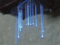
Accordingly,
a ferrule-connector system can be not only far easier to use, but better for
experimental success. In this scenario, an optical fiber (stripped down to
the cladding) is attached to a metal or ceramic ferrule (see Figure
1, below), and inserted into the brain chronically. Ferrules can be bought
from many companies (e.g. 140 micron or 230 micron stainless alloy
ferrules are parts F1-0063F-25 or F1-0064F-25 from http://www.fiberoptics4sale.com/;
another vendor is Kientec
Systems, http://www.kientec.com/ceramics.html,
from which we often get 225 micron inner-diameter ferrules, e.g. part number
FZI-LC-225 (which stands for, F(ferrule)ZI(zirconia)LC(ferrule type)225(inner
diameter))), and come in both steel as well as nonmetallic zirconia
forms. You attach the ferrule to the fiber in a process similar to the
way that you attach an optical fiber to an FC/PC connector (see above
instructions relating to the Thorlabs
fiber “Polishing and Connectorization
Guide”). Below, in section 1.e. is our current step-by-step
protocol for attaching a ferrule to a fiber.
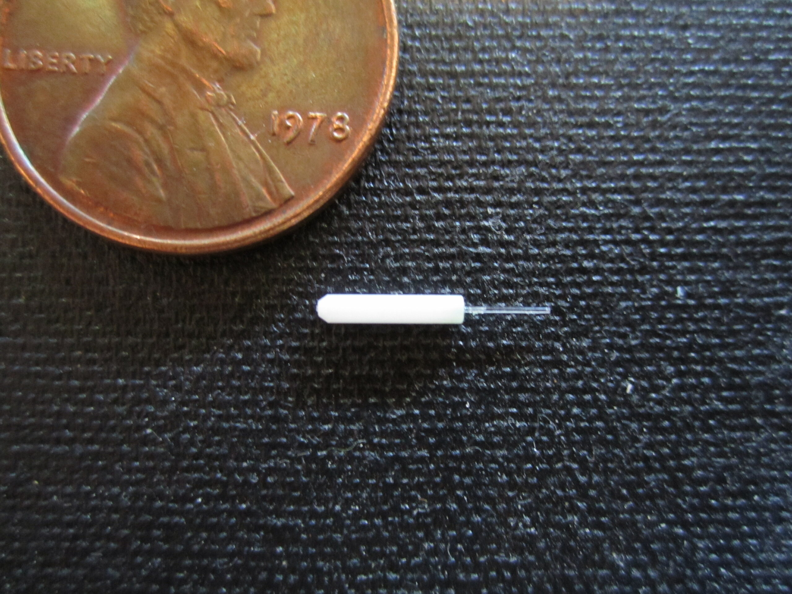
Figure 1. A ferrule
attached to a piece of fiber. The ferrule shown is from Precision
Fiber Products, and is a 1.25mm OD Multimode Ceramic Zirconia Ferrule (part
MM-FER2007C, e.g., http://www.precisionfiberproducts.com/ccp0-prodshow/ferrulestickMM125OD.html).
The fiber is from ThorLabs,
BFH48-200 Multimode Fiber, 0.48 NA, 200 micron core.
The
fiber can then be chronically implanted into the brain, with the ferrule
sticking out (the pointed end points away from the brain), during a surgery,
attaching the ferrule to the skull or to skull screws using dental acrylic.
Attach
a similar ferrule to the end of the fiber that is connected to the laser, using
the very same fiber connectorization/polishing
protocol (see 1.e., below, for details). The pointed end of the
ferrule should point away from the laser.
Then,
just before the experiment, you can then use a zirconia split sleeve (e.g.,
F1-8300SSC-25 from http://www.fiberoptics4sale.com/,
or http://www.optequip.com/products/connector_kit_pigtail_A10046.htm,
depending on the ferrule size you choose) to connect the ferrule that is attached
to the fiber implanted in the animal, to the ferrule attached to the end of the
fiber that connects to the laser. If
you are using the aforementioned optical commuator (or rotary joint, Doric
Lenses), you can order its fiber to terminate with such a ferrule ending.
You can also use larger, more conventional, connector strategies to join the
two fibers, but these can be more bulky.
1.e. Current protocols
for attaching ferrules to fibers
The
following protocol is a practical, expedited form of the Thorlabs Polishing and Connectorization Guide, streamlined for attaching
ferrules to fibers as in Figure 1.
1.
Take a ferrule, e.g. a 225 micron inner diameter ferrule from Kientec Systems. The ferrule
should have a pointed end (which will be the side that serves as the connector)
and a flat end (which will be the side that is aimed towards the brain).
2.
Take spool of optical fiber, e.g. 200 micron fiber from Thorlabs. Strip off 1.5-2 cm of coating from the
fiber, using a razor blade, or a fiber stripper. Score the stripped fiber with
a diamond scribe, and pull off the piece of stripped fiber, from the spool
(thereby cleaving the fiber off).
3.
Insert the stripped fiber into the ferrule, so that about an appropriate length
of fiber (i.e., appropriate to hit the neural target) sticks out from the flat
end.
4.
The next step is to get adhesive into the ferrule, to lock the fiber in.
There are many ways to do this. Two are described here – you get the idea:
4a. One way is to brush some
Loctite 7649 Primer onto the fiber, at either point where it enters the
ferrule. Let it evaporate. Then squeeze some Loctite 680 retaining
compound onto each end of the ferrule, so that it seals the fiber inside the
ferrule (but avoid getting the Loctite 680 on the end of the fiber). Dab
off excess Loctite 680 and let dry.
4b. Alternatively,
apply some waterproof epoxy as a tiny bead on each end of the ferrule, to lock
the fiber into the ferrule. Once it cures, load some waterproof epoxy
into a syringe with a needle (e.g., 20 gauge), and flood into the ferrule to
completely seal the fiber in the ferrule (avoiding getting any on the fiber, as
much as possible).
5.
As in #2, cleave the fiber coming out of the pointed end of the ferrule (by
scoring and pulling, or snapping if pulling, in your hands, causes the fiber to
come out), as close to the end as possible.
6.
Polish the fiber emerging from the pointed end of the ferrule, using 5 micron,
then 3 micron, polishing film (from the Thorlabs
connector kit, if you are doing this for the first time; you can buy the raw
materials from the kit if you like), until the fiber tip is flush with the end
of the ferrule, and feels smooth. The epoxy should be gone from the pointed
end of the ferrule, by this point (check periodically under a dissection
microscope to gauge progress).
You can do this by hand, or use the “polishing plate” in the Thorlabs kit to get a very fine
and flat finish. You can also optionally use the 0.3 micron polishing
film to get an even finer finish (you can add a few drops of pure water to the
polishing paper to help).
7.
You can re-cleave the fiber end that protrudes from the flat end of the ferrule
to get a fresh end, with the exact length that you want, if you like, at this
point.
8.
Check power output by coupling the ferrule to a ferrule attached to a fiber
attached to a laser, to observe the power output.
2.
Controlling the laser
2a.
NIDAQ
For a TTL-controllable laser: you can control it
easily with any TTL-pulse-outputting device. This is a
commodity – you can use the Molecular Devices Digidata, for example, if you have a patch clamp rig
already there, or most other pulse generators. NiDaq boards are easy to use and inexpensive, and many
labs have them already. Or if you have any kind of pulse generator (e.g.,
Master-8) or function generator, you can control a TTL-controllable
laser. For NiDaq boards: it’s easiest to
program them through Labview, or through the National Instruments calls from MATLAB (Data
Acquisition Toolbox).
NiDaq boards: many of them will
suffice for TTL control of lasers. For analog control, consider the following:
NI USB-6211 (up to 250ksamples/second analog
output)
NI USB-6221 (even faster)
And so forth.
2b.
Arduino
Another
popular strategy for controlling the laser is to use Arduino boards. Arduino boards (Google it, or you could try this
link http://www.google.com/search?q=arduino+sparkfun)
are little programmable boards that take in lots of inputs (analog and
digital), can send out lots of outputs, and are easy to program. They
just plug into your computer over USB. (Check out the Arduino Lilypad
from Leah Buechley – she
has developed a fantastic kit for teaching kids how to make robots and sensors
and other computational devices, e.g., you could try this link http://web.media.mit.edu/~leah/LilyPad/.)
Even if you don’t know how to program, there are tons of examples of code
online. And the boards are only about $25 – very cheap (NI board will
often cost $1000-$2000). And they can be used to control behavioral
stimuli (tones, lights, doors, fear conditioning equipment, etc.), just as easily.
2.
THE INJECTOR
If
you want a good, simple, single point injector, use the UMP3-1 stereotax-mounted injection pump
with controller from WPI. In order to have a 35 or 36 gauge needle you
need to order from WPI along with their 10 microliter syringe; the needle tip
is easily bent, however, making consistent injections over a long period of
time unlikely. Somewhat more robust: you can insert a bigger-gauge
Hamilton syringe directly into the pump (use a 33 gauge needle, say), and it
can then suck up and inject
virus. (E.g., you can get a Hamilton 33-gauge needle six pack (7762-06)
and a 10 microliter syringe (7653-01) from www.hamiltoncompany.com/Syringes.)
If
you want a powerful, flexible, but harder to use pump that can infuse virus
through flexible polyethylene tubes attached to syringes mounted in the pump,
use the Harvard Apparatus PhD2000 displacement pump. Place the syringes
in the pump, attach tight-fitting polyethylene tubes to them, and insert thin
needles (36 gauge steel cannulas, or pulled glass micropipettes) into the ends.
In
either case, fill the entire apparatus with silicone oil or another oil so that there is no air in the
system. Then at low speed suck the virus into the tip of the
needle. Insert the needle into the brain like an electrode. Infuse
slowly (0.1 uL/min), then
wait 10-30 mins afterward
for the virus to diffuse, before withdrawing the needle slowly.
3. Validating temperature in the brain
It
can be of great use to validate temperature in the brain, as light can induce
heat. You can obtain thin needle thermocouples that can be inserted into the
brain, even near a fiber, to measure temperature at defined points in the brain. The thermocouple we recommend is the HYP0-33-1-T-G-60-SMP-M
on this page: http://www.omega.com/pptst/
it does not record from the very tip of the probe. The shaft is in fact a 33
gauge needle, with the thermocouple junction inside it not quite all the way to
the tip. The other part of the system
that is required is a thermocouple data logger. Many digital acquisition
systems can do this, but often sample at a relatively low rate on the order of
1Hz. To record much faster (up to hundreds of Hz), we use the iNET-100 data
logger, though it’s old and not very user friendly (you can try this link: http://www.omega.com/ppt/pptsc.asp?ref=INET-100&Nav=dasc01
).
This document describes systems for in vivo light delivery that are inexpensive and relatively easy to use. The goal is to provide the least expensive, most current, helpful information about systems you can use for in vivo optical neuromodulation. We will try to update this document every now and then, so that what you see below represents the best practices of the field. Please note, part numbers for products are liable to change at any time; contact the manufacturer for updates, and please notify the authors of this white paper as well. Feedback always welcome!