© 2006-2008, Synthetic Neurobiology Group, MIT Media
Lab/BCS/BE, MIT.
Contact info: Ed Boyden, esb@media.mit.edu
IMPORTANT: Unless you are an
expert at optics (and even if you are) we highly recommend that you use, or at
least first consider, the alternative protocol, “Very Simple Off-The-Shelf
Laser and Viral Injector Systems for In Vivo Optical Neuromodulation” (see left). The principles described in the document are still of general interest.
0. Introduction
This two-laser, one fiber system is optimal for doing
utilization of the blue-light activator channelrhodopsin-2 and/or the yellow-light
inhibitor halorhodopsin (and future derivatives thereof) at the same time. In
this way, bi-directional control of a single point in the brain can be
performed, using ‘optogenetics’ technologies. This setups saves thousands of
dollars, and is more flexible and powerful, than commercial single-color
fiber-coupled lasers. In addition, the setup can be used (carefully) in an
MRI-compatible fashion.
It is also appropriate for using halorhodopsin with
blue-light resetting, which prevents run-down with extended illumination of
halorhodopsin with yellow light, as demonstrated in Figure 5 of
Han, X. and Boyden, E. S.,
Multiple-color optical activation, silencing, and desynchronization of neural
activity, with single-spike temporal resolution. PLoS ONE, 2007. 2(3): p. e299.
PMCID: PMC1808431.
In general, multiple colors of light will increasingly be
useful for driving multiple biological activities simultaneously.
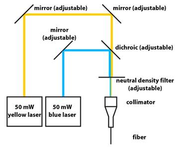
1. Schematic:
2. Lasers are from Shanghai Dream Laser:
Tel: +86-21-37601510
Fax: +86-21-57600170
www.dreamlasers.com
DPSS 593nm Orange laser
TTL modulation at 10 kHz
50mW
SDL-593-050T
DPSS 473nm Blue Lasers
TTL modulation at 10 kHz
50mW
SDL-473-050T
NOTE: Shanghai Dream Laser lasers are inexpensive,
but if you pulse them, the power will depend on the pulse duration (e.g., the
laser takes time to ramp up, and that makes short pulses weaker than longer
pulses). Accordingly, it is important to characterize the power as a function
of pulse duration and pulse repetition rate.
3. From Thorlabs:
Three mirrors – BB1-E02 1″ Diameter Broadband Dielectric Mirror,
400-750 nm
Two of the mirrors help steer the two beams into
the fiber (see schematic above).
The other two mirrors can be placed, one each,
in front of the lasers, to facilitate alignment.
Four mirror mounts – KM100 Kinematic mirror mount for
1 inch optics
Mount the mirrors and the
dichroic (see below, from Chroma) on the kinematic mirror mounts. It is
necessary to mount the dichroic, which does not fit in the 1” optics mount, by
attaching it to a corner of the mount with double sided sticky tape or a drop
of super glue.
Collimator is made out of:
a. Collimator – F240SMA-A
8.0mm focal length SMA Fiber Collimation Pkg
b. Adapter – AD12F – SM1
Adapter for Ø12 mm Collimators
c. Lens tube – SM1L10
Lens Tube, ø1″, 1″ Long
d. Lens tube mount – KM100T
Kinematic mount for 1” optics
Optical fiber –we use .48NA optical fiber – BFH48-200.
a. Tool to strip the
coating – T12S21 – Fiber
stripping tool (Clad/Coat: 250/500µm),
b. Tool to cleave the
fiber – S90W – Diamond wedge scribe
c. Illustrated
cleaving instructions – FN96A – Guide to Connectorization and Polishing of
Optical Fibers
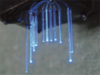
We do not polish the end of the
fiber which interfaces with the brain after cleaving because cleaving suffices
for making a very smooth optical surface (with some practice).
Optical Power Meter: PM100D – Power meter console
S121C – Photodiode sensor,
500nW-500mW range. The S121C is a good general-purpose photodiode. Although
it is not ideal for measuring power output from optical fibers because the beam
diverges, you can get a very close estimate to the total power output by
holding the end of the optical fiber right in front of the center of the
photodiode.
Neutral Density Filter – NDC-50C-2M Mounted
Continuously Variable ND Filter, D:0-2.0
The neutral density filter wheel enables
easy control of the output power of the optical fiber, since you normally want
to shine less light on the brain than the lasers can output.
You’ll need assorted posts and post holders (best to buy a
kit with various heights), and a breadboard (say, at least 2 feet by 1 foot,
with 1”-spaced holes) to hold everything. You may also, depending on the laser
models you use, want to use sheets of aluminum to raise the lasers up to the same
height, to simplify the mirror tuning.
4. From Chroma:
Dichroic filter – a sharply-tuned GFP dichroic filter will
do (e.g., reflects blue, passes yellow).
Note: The laser beam is small; a
single dichroic filter can be cut into multiple pieces if desired.
5. From oceanoptics.com:
Fiber termination kit – TERM-KIT – so you can put an SMA
connector on the end, to fit in the Fiber adapter above. See http://www.oceanoptics.com/products/fiberkits.asp#termination
6. Laser Safety:
The class IIIb lasers recommended in this paper can cause
blindness if improperly operated. Your institution may also offer classes on
laser safety. Regardless, when setting up a laser system for the first time,
it is best to enlist the help of an expert. Handling, cleaning, and aligning
optics are laboratory skills that must be learned hands-on.
7. Alignment Tips:
Couple the blue laser to the fiber first. Then couple the
yellow laser by aligning it to the same path as the blue beam after the
dichroic. Insert a sheer piece of lens cleaning paper into the beam path to
visualize the location of the blue and yellow beams. Manipulate the two
mirrors on the yellow beam path before the dichroic such that the blue and
yellow beams are coincident just after the dichroic and just before the
collimator.
This two-laser, one fiber system is optimal for doing utilization of the blue-light activator channelrhodopsin-2 and/or the yellow-light inhibitor halorhodopsin (and future derivatives thereof) at the same time. In this way, bi-directional control of a single point in the brain can be performed, using ‘optogenetics’ technologies. This setups saves thousands of dollars, and is more flexible and powerful, than commercial single-color fiber-coupled lasers. In addition, the setup is MRI-compatible.